Spi-Ro T-40 Traps in a Multiband Dipole
By Paul Bock,
K4MSG of Hamilton, Virginia, November 26, 2011
Click here for other articles by Paul posted to the LARG Internet Site
BACKGROUND
Following a recent experience with a multiband trap dipole that failed due to a mechanical problem in one of the traps, I decided to create a new antenna using a different type of trap. The antenna that failed used Unadilla KW-40 traps, the mechanical design of which lends itself to failure if the plastic housing on which it is built fails by cracking apart, as happened with mine.
My initial thought was to design and build a new trap but I happened upon Spi-Ro Manufacturing, a company that sells antennas, antenna accessories, parts, etc. Among their products are antenna traps intended for multiband dipoles and one of them, the T-40, is for use in an 80/40 meter dipole that can also operate on 20, 15 and 10 meters with "somewhat higher VSWR." Although more expensive than Unadilla traps ($76/pair versus $52/pair), the mechanical design seemed more robust so a pair was ordered.
Photo 1 illustrates the T-40 trap. The electrical components are housed inside a 7.25-inch length of 1.25-inch OD PVC pipe with PVC end caps glued on. Connections are made to threaded brass fittings on each end which carry 10-24 brass screws. A close-up of the wire connection to the brass fitting is shown in Photo 2. The trap has a design frequency of 7 MHz and is rated at 600 watts.
DESIGN & ASSEMBLY
The dimensions given in the data sheet for an 80/40 meter dipole seemed a bit short based on my past experience with trap dipoles, and an email to the company confirmed that these dimensions were for the center of the phone bands on 80 and 40 meters. Since I wanted the antenna resonant at the CW end of each band I factored extra wire into my design plan and constructed the antenna using inner sections of 34 feet each and outer sections of 23 feet each.
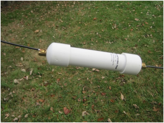
Photo 1: Spi-Ro T-40 antenna trap.
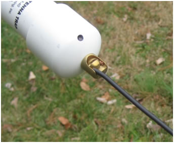
Photo 2: Close-up of wire connection.
The antenna was assembled using two Spi-Ro T-40 traps, No. 14 stranded & insulated copper antenna wire from DX Engineering, and a Radio Works B1-200 200-watt current balun, and installed in place of the existing trap dipole. After installation and testing I determined that the center points were below the lower CW band edges on both 80 and 40 meters. 40 meters was adjusted first by trimming the inner sections a few inches at a time until the minimum VSWR point was about 7040 kHz. The total amount trimmed from each side was 12 inches, so the final length of the inner sections was 33 feet each.
After adjusting the 40-meter (inner) sections, a check showed that the minimum 80-meter VSWR point had risen to just above 3530 kHz - great for low-end CW DXing, but at the highest CW net frequency of 3578.5 kHz the VSWR was 2.5. Trimming 3 inches from each outer section raised the minimum VSWR point to 3550 kHz, leaving a VSWR of about 1.85 at the highest net frequency used. Trimming the outer sections had no effect on 40 meters and the outer section lengths ended up at 22 feet, 9 inches.
The antenna's VSWR performance on six bands of interest is shown below. These numbers are with no antenna tuner in use. When the built-in ATU in my Icom IC-756 Pro is used a 1.0 VSWR is obtainable on any part of any of the bands shown. The 17 and 12 meter bands were not tested because I never use them, and while they might be tunable with the ATU the VSWR between the coax and the antenna is probably very high (as it is on 30 meters).
80 meters 3500 kHz = 2.4, 3513 = 2.0, 3550 = 1.7, 3583 = 2.0, 3600 = 2.5
40 meters 7000 kHz = 1.3, 7040 = 1.0, 7100 = 1.6
30 meters VSWR > 5 @ 10110 kHz (definitely a compromise on this band)
20 meters 14000 kHz = 2.3, 14100 = 2.7
15 meters 21000 kHz = 2.0, 21100 = 2.1
10 meters 28000 kHz > 5, 29750 = 2.0
ANTENNA SUPPORT DESIGN
Since a lot of raising and lowering of the antenna is required to trim and test, trim and test, etc., what follows is a description of how my wire antennas are installed. I support the antenna using black Delrin blocks roughly 3 inches square which are cut from quarter-inch flat Delrin stock. The blocks are each drilled with a small hole for a support rope to anchor the block at the antenna support point in a tree, and also a larger 3/8-inch hole with chamfered edges for the antenna support rope to pass through. This arrangement allows the antenna to be easily raised and lowered from either end for repair or replacement.
Photo 3 shows a Delrin block mounted high in a tree and supporting an antenna. The block support line, which in the photo passes through a fork in the tree, is plainly visible to the left of the block while the antenna support rope is visible to the right and then vertically after it passes through the larger hole in the block. Both ropes are tied off at the bottom of the tree as shown in photo 4.
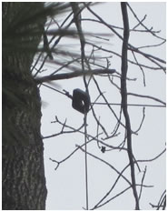
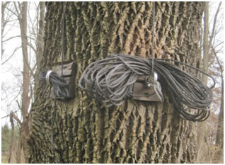
Photos 3 & 4: Antenna support block and support ropes.
Installation of a block involves dropping a line over the fork or branch chosen to support the antenna, and pulling the block up to within a few inches of the tree with the antenna support line already fed through the larger hole in the block. With the block support line tied off at the base of the tree, the antenna support line is easily pulled up taut or let out through the large hole in the block, and if the tree eventually grows over the block support line the worst that can happen is that the block becomes permanently attached to the tree.
The antenna support line is 3/16-inch black Dacron and when it starts to show wear or heavy fading I replace it to preclude breakage, since such a failure might cause the line to "run" completely out of the block and necessitate either climbing the tree to reinsert it through the block or installing a replacement block using the procedure above (to avoid having to climb the tree).
ON-AIR PERFORMANCE & CONCLUSION
The new trap dipole seems to work quite well, in fact noticeably better than the old one using the Unadilla traps. During the testing and adjustment phase I found that this antenna behaves very predictably and responds smoothly to the trimming process with no sudden or unexpectedly large changes in VSWR as long as it is trimmed a few inches at a time. With the antenna tuned as it is the 80-meter performance will allow traffic net operation even if the tuner fails because the VSWR will be less than 2 on the usual net frequencies, and the transceiver's ATU will easily tune the lower portion of the CW band to 1.0. On 40 meters the tuning is so broad that the entire CW portion can be covered easily with no tuner required. I was also gratified to note that on 20 and 15 meters - especially the latter - the VSWR is not unacceptably high even without a tuner. This means that the antenna can be expected to perform fairly well on those bands since reflections from the antenna feed point are modest, and of course the ATU makes the transmitter end of the coax look like VSWR = 1.
One final note on the antenna wire support points on the traps, i.e., the brass screws shown in Photo 2: The screw heads are large (they are round-head screws) and there is only a small clearance between the edge of the head and the sides of the brass collar into which the screw is threaded. The result is that the copper antenna wire is held very firmly when wrapped clockwise around the screw body using an exposed copper length of about 0.75 inch. Because the attachment is copper-to-brass there will be minimal galvanic corrosion and the fact that no soldering is required means that the copper antenna wire isn't weakened by heating it.
This antenna is quick and simple to assemble, requires no soldering, and performs very well - and that's hard to beat.
NNNN