EME on a Budget:
Moonbounce for the Rest of Us
By
Paul Bock, K4MSG
PART I - INTRODUCTION, OPERATIONAL
BASICS AND PROPAGATION
The purpose of this article is to provide radio amateurs
with enough background information to understand the technical challenges
involved in "small-station" digital EME on the 144 and 432 MHz bands. Suggested configurations, approximate costs
and operational potential will be included, all with the goal of encouraging
amateurs to consider EME by showing that it is neither excessively complex from
a technical perspective nor prohibitively costly when compared to other amateur
activities. The article also includes a
brief overview of the author's operational success to date.
A BIT OF HISTORY
Since
the first successful amateur radio two-way EME (Earth-Moon-Earth or
"moonbounce") communications in the early 1960s, EME has been regarded as the
pinnacle of technological challenge as well as an activity requiring
substantial financial resources. The
latter is due to the necessity of overcoming the huge path loss (~250 dB) involved
in sending a radio signal to the Moon and back. Initially this meant a massive antenna array, full legal transmit power,
and state-of-the-art technology to attain the lowest possible receiver noise figure.
Achieving all of these goals still meant
that only CW contacts were possible because of the faint return signals,
sometimes buried in noise, which required excellent hearing to detect.
Beginning in the 1970s, however, several things happened
to begin to make EME possible for those with somewhat lesser capabilities (and
with less expenditure):
1. The gradual development around the world of EME
"super-stations" having huge arrays and the best state-of-the-art equipment
that money could buy, allowing them to complete EME CW contacts with many less-well-equipped
stations.
2. The development of the gallium-arsenide field-effect
transistor (GAsFet) and other devices that made significantly lower noise figure
VHF/UHF preamplifiers practical.
3. The development of high-quality affordable coaxial
cable with lower loss at VHF & UHF.
4. The publication of practical designs for VHF and UHF
kilowatt amplifiers that a reasonably technically-astute ham could build.
While
the above technological improvements made EME more affordable and "do-able" by
more hams willing to take on the challenges, it wasn't really until the
development in the late 1990s of the WSJT series of digital transmission
protocols by Joe Taylor, K1JT, that "everyman" use of the more esoteric weak-signal
VHF/UHF communications modes - meteor scatter and EME - started to become more practical
and affordable. These digital protocols
allow the reception and accurate decoding of signals far below the noise level,
as low as -24 dB and sometimes beyond.
While
VHF meteor scatter was always possible during the major meteor showers - especially
on CW - for anyone with a good Yagi antenna and 100 watts of power, the WSJT JT6M
and FSK441a protocols fulfilled the dream of 50 and 144 MHz QSO completions
using random daily meteors; i.e., the thousands of "grain of sand" micrometeoroids
that enter the atmosphere every day and create usable ionized trails of 100
milliseconds or less. The
near-simultaneous development of the WSJT JT44 and JT65 (a, b and c) protocols did
much the same for EME that JT6M and FSK441a did for meteor scatter. It is now possible for an amateur with 100
watts and a single Yagi with at least 12 dB gain to work any of the really
large EME stations and, when conditions are favorable, some of the more modest
stations as well. For a single-Yagi EME station
to successfully contact a 4-Yagi station still requires excellent conditions, skillful
operating and a bit of luck, but it is being be done on 144 MHz.
Because of the increasing popularity of EME any ham with
a modest station somewhat larger than the "minimum" to be described can,
through perseverance, achieve EME DXCC and some operators have completed EME
WAS. Even a station such as the one
described should be able to accumulate enough "grid squares" by means of meteor
scatter and EME to augment terrestrial operation and qualify for 144 MHz VUCC (and
using EME, even 432 MHz!) without raising a tower or running full legal power.
EME OPERATIONAL CHARACTERISTICS & LUNAR
AVAILABILITY
It is important that anyone interested in EME understand
the "operational characteristics" of using the Moon as a reflector for two-way
communications. Below is a short list of
the major concerns.
1. BOTH
STATIONS MUST "SEE" THE MOON. This may seem like a superfluous statement
but it bears repeating that the Moon *MUST*
be above the horizon at both ends of an EME QSO.
2. The Moon's position changes daily and the rising &
setting times advance day by day by about a half-hour to an hour depending on
the time of the month. This will impact
potential operating times and depending on personal schedule may limit one's
"on-air" availability.
3. Due to the Moon's rotational schedule relative to
sources of celestial noise and the Sun the Moon is only available and useful
for EME operation for about 20 days per month.
The
two illustrations that follow should give a pretty good idea of how the Moon's
usefulness for making two-way EME contacts varies over a one-month period. The first illustration is a table of Moon
rise and set times and the corresponding azimuth of the Moon for each. You can access the table for May, 2013, at
the link below and just enter the desired month and year in the appropriate
boxes.
http://www.timeanddate.com/worldclock/astronomy.html?n=263&month=5&year=2013&obj=moon&afl=-12&day=1
The second illustration is a screen shot of the EME
display window at the "Make More Miles on VHF" web page at http://www.mmmonvhf.de/eme.php. This
particular shot is also for the month of May, 2013, but can be changed by
entering a different month & year.
|
Date |
Moonrise |
Moonset |
Moonrise |
Moonset |
Phase |
|
May 1, 2013 |
1:09 AM |
11:46 AM |
111° |
250° |
|
|
May 2, 2013 |
1:51 AM |
12:53 PM |
107° |
256° |
Third Quarter at 7:15 AM |
|
May 3, 2013 |
2:28 AM |
1:59 PM |
101° |
261°
|
|
|
May 4, 2013 |
3:01 AM |
3:02 PM |
96° |
267° |
|
|
May 5, 2013 |
3:33 AM |
4:04 PM |
90° |
273° |
|
|
May 6, 2013 |
4:04 AM |
5:05 PM |
84° |
279° |
|
|
May 7, 2013 |
4:35 AM |
6:05 PM |
78° |
284° |
|
|
May 8, 2013 |
5:08 AM |
7:04 PM |
74° |
289° |
|
|
May 9, 2013 |
5:44 AM |
8:02 PM |
70° |
292° |
New Moon at 8:29 PM |
|
May 10, 2013 |
6:23 AM |
8:57 PM |
66° |
295° |
|
|
May 11, 2013 |
7:05 AM |
9:49 PM |
64° |
296° |
|
|
May 12, 2013 |
7:52 AM |
10:37 PM |
64° |
296° |
|
|
May 13, 2013 |
8:41 AM |
11:20 PM |
64° |
295° |
|
|
May 14, 2013 |
9:34 AM |
- |
66° |
- |
|
|
May 15, 2013 |
- |
12:00 Midnight |
- |
292° |
|
|
May 16, 2013 |
- |
12:36 AM |
- |
289° |
|
|
May 17, 2013 |
- |
1:09 AM |
- |
284° |
|
|
May 18, 2013 |
- |
1:40 AM |
- |
279° |
First Quarter at 12:35 AM |
|
May 19, 2013 |
- |
2:11 AM |
- |
274° |
|
|
May 20, 2013 |
- |
2:42 AM |
- |
268° |
|
|
May 21, 2013 |
- |
3:15 AM |
- |
262° |
|
|
May 22, 2013 |
- |
3:51 AM |
- |
256° |
|
|
May 23, 2013 |
- |
4:31 AM |
- |
251° |
|
|
May 24, 2013 |
- |
5:18 AM |
- |
247° |
|
|
May 25, 2013 |
- |
6:12 AM |
- |
244° |
Full Moon at 12:25 AM |
|
May 26, 2013 |
- |
7:14 AM |
- |
244° |
|
|
May 27, 2013 |
- |
8:21 AM |
- |
245° |
|
|
May 28, 2013 |
- |
9:31 AM |
- |
249° |
|
|
May 29, 2013 |
10:41 AM |
254° |
|||
|
May 30, 2013 |
12:28 AM |
11:49 AM |
103° |
259° |
|
|
May 31, 2013 |
1:03 AM |
12:55 PM |
98° |
265° |
Third Quarter at 2:59 PM |
The
first thing you should note from the table is that the Moon rises later and
later each day. This means that if you cannot
adjust your antenna in elevation and/or wish to take advantage of any "ground
gain" (described later) by operating at Moonrise or Moonset you will be doing
it anywhere from approximately 30 to 60 minutes later each successive day
depending on the day of the month.
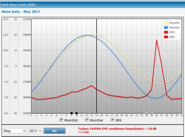
The screen shot shows the Moon's Distance (yellow line),
Declination (blue line) and Degradation (red line) and is useful for
determining what days are best for attempting operation. The smaller degradation peak occurs when the
Moon is roughly coincident with the Sun, while the very large peak occurs when
the Moon is passing in front of the Milky Way, a *HUGE* source of galactic
noise! The best days for small stations
occur when the Degradation is 2.5 dB or less. It is possible to have some success with the larger stations at
degradations of 3 dB or so but when the degradation is above 4 dB it is going
to be very, very tough to make QSOs - not because you cannot copy stronger
stations, but because your "small station" signal is normally right at the
decoding limit and any small amount of additional noise will push your signal
into oblivion. Using this description of
limitations you can see that for the month of May, 2013, the Moon is potentially
usable for a small station from May 1 - 8 (8 days), May 16 - 24 (9 days), and
May 28-31 (4 days) for a total of 21 days, although actual "useful days" will
likely be fewer.
While the above are useful tools for helping you to decide
when to plan your EME operation, there are still propagation issues that can
nullify your attempts even on the best of days. When you are running a single Yagi at low power there will be times when
you will get absolutely nowhere, but don't be too discouraged; just be patient
and keep trying, and you *WILL* make QSOs!
PROPAGATION ISSUES WITH EME
There is little debate among those who have "taken the
plunge" in EME that the propagation challenges can be both formidable and
unpredictable. Over the decades many
hams have labored tirelessly to try and quantify, to the extent that such is
possible, the vagaries of propagation associated with bouncing radio signals
off of our nearest neighbor in space. What follows are some short descriptions of what these phenomena are and
how they can affect the EME equation.
Orbit (Perigee - Apogee)
The Moon orbits the Earth approximately once every 28 Days in a
slightly elliptical orbit. At Perigee (the closest the Moon approaches the Earth)
the 144 MHz path loss approaches 251.5 DB; at Apogee the value reaches 253.5
DB. Believe it or not, this 2 dB variation can mean the difference between
completing a QSO or not when other factors drive signal levels down.
Faraday Rotation
As the signal passes through the Ionosphere it rotates in polarity
both on the way up and on the return bounce. The amount and speed of the
rotation are always shifting and are unpredictable. When using arrays of fixed
polarity (such as horizontal, which is most common) it is necessary to wait for
the polarity to rotate into phase for reception. At times this never happens and you are
effectively locked out, regardless of how large your station antenna array may
be. This is due to up to 20 dB difference
between vertical and horizontal polarization. Attempting to contact another
station complicates the situation even more as now the signal must pass through
two different ionospheric areas before arriving at either antenna.
Spatial Polarity
First proposed by KL7WE and K9XY in
1984, this phenomenon is the reason why stations are audible at one location and
not another. Imagine you are on the Moon looking at North America; a station
there using horizontal polarization is pointed at you and his wavefront arrives
horizontal. Now look at the station in
Europe using horizontal polarization and compare his wavefront to that of the North
American station and you will see that they appear to be out of phase. At times
the two polarities are 90 Degrees out of phase and thus 20 DB down from one
another. That is far too much for the average EME station to overcome so no QSO
takes place - EXCEPT for Faraday rotation, which can rotate the wavefront into
the proper polarity and allow contact to be made. The fact is that due to the Spatial Polarity
effect, without Faraday rotation most EME contacts would never happen.
Libration Fading
There is a random fading effect on
signals received off of the Moon caused by the rocking motion of the Moon and
the signal wavefront bouncing off of the Moon's jumbled surface and taking on an
irregular shape itself. The distorted wavefront is now full of peaks and nulls
which sometimes add up in phase although on the average they give a 7% Pi-R-Squared
reflectivity. However, when the phase additions occur the overall path loss can
be REDUCED by as much as 6 to 10 DB.
Sky Noise
As the Moon travels in its orbit the surrounding sky is filled
with the random radio frequency noise emitted by all of the stars and galaxies. Some celestial bodies are noisier than others
and any additional noise adds up as so many DB of degradation to your system.
Measured in degrees Kelvin it can vary from 170 or so to as much as 3000+
degrees. The Milky Way is by far the biggest contributor and when the Moon is
in its vicinity communications is impossible even for the largest stations. When
the Moon is near the Sun there is also more noise so those days may be unusable
as well. It should be noted that on 432
Mhz and above celestial noise poses less of a problem as the sky temperature in
degrees K goes down in proportion to an increase in frequency.
Scintillation
When a radio wave from a distant source
such as the Moon reaches the ionosphere the phase surface of the wave is
distorted by irregular patches of varying refractive index. Since these patches
are constantly moving the result is an interference effect resulting in fading
known as Amplitude Scintillation. This is analogous to the visual "twinkling"
of the light arriving from stars. It is
possible for the effect to be additive and when this occurs it can result in up
to 10 dB of non-reciprocal enhancement of an EME signal.
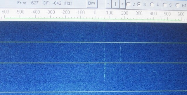
Doppler Effect
At Moonrise the Doppler effect between the Earth and Moon at 144
MHz will cause the echos to appear 300 Hertz or so higher in frequency. As the Moon traverses the sky to a point due
south the Doppler approaches zero, and as the Moon continues westward the echos
shift up to 300 Hertz lower in frequency at Moonset. This can pose a problem for the operator who
answers a CQ where he/she is hearing the station but is not allowing for
Doppler and is calling a station using very narrow filter bandwidth. The solution is to always shift the receiver
RIT to correspond to the Doppler (which is indicated by the JT65b operating
window on the computer).
Moonrise / Moonset - 6 dB Ground Gain
In
Part II we'll take a look at how a "beginner"144 MHz EME station might be
configured, what it will cost, and how the K4MSG EME station was initially
configured.
EME on a Budget:
Moonbounce for the Rest of Us
By
Paul Bock, K4MSG
PART II - A BASIC 144 MHz EME STATION
STATION REQUIREMENTS
This
section begins with an outline of station requirements because for many readers
the bottom line is going to be - well, the "bottom line." Later on I'll discuss the details of how my
station is assembled and outline the basic set-up requirements, but if the
projected costs discussed in the following paragraphs are too much of a
"turn-off" for any reader to consider then there is no point in him or her
going beyond this part.
1.
A VHF
multimode transceiver capable of 144 MHz SSB operation, with output sufficient
to drive an outboard amplifier. IF A HIGH STABILITY REFERENCE OSCILLATOR
OPTION IS AVAILABLE IT WOULD BE PRUDENT TO PAY THE EXTRA MONEY FOR THIS
CAPABILITY. In Digital EME as in so
many other things in life, "timing is everything."
2. A combination power amplifier & low-noise
preamplifier (aka a "brick") having a power output of 100 watts or more and a
preamplifier noise figure of less than 1 dB (and the lower, the better). THE UNIT SHOULD BE INSTALLED AT
THE ANTENNA. (NOTE: Don't panic,
this is much easier than it sounds.)
3. A DC power supply to be situated outside to power the
amp/preamp.
4. A Yagi antenna with a forward gain of at least 12
dBd. THE ANTENNA ONLY NEEDS TO BE MOUNTED 7 TO 10 FEET ABOVE THE
GROUND.
5. A small rotor for azimuth adjustment of the antenna (a
TV rotor will suffice) is recommended although manual azimuth adjustment can be
used if not too much of an annoyance. Some form of elevation adjustment is recommended, even if only manual,
but EME contacts can be made during the first hour after Moonrise or the last
hour prior to Moonset without it.
6.
The shortest possible
(50 feet or less is a good rule of thumb) low-loss coax between the transceiver
and the amp/preamp. "Low loss" means, AT
A MINIMUM, Belden 9913. LMR-400, EcoFlex
10 Plus and AirCom Plus are better still.
7. A radio/PC interface controller such as a Rigblaster
by West Mountain Radio.
8.
A desktop or
laptop PC installed at the operating position. Windows XP or later are recommended operating systems, and WSJT Version
9 (which is FREE from the WSJT website) should be installed.
9. An accurate time-stabilization program (such as
Dimension 4, which is also free) should be installed on the PC.
Here
is how the basic costs break down:
1. TRANSCEIVER: Whatever you choose to spend.
2. AMP/PREAMP: Up
to $450 new depending on brand; less
if purchased used.
3. POWER SUPPLY: Up to $200 for a new
linear-type. I paid $105 shipped for a
new MFJ switcher (compact, reliable, and there are *NO* noise problems with
it!).
4. ANTENNA: $225-$250 including shipping and/or local
sales tax (if bought from HRO).
5. TV ROTOR: ~$100.
6. LOW-LOSS COAX: ~$60-$120 depending on type and length.
7. INTERFACE UNIT: $160 for a Rigblaster Plus
II.
8. PC/LAPTOP: Whatever you choose to spend.
9. WSJT and Dimension 4 software: FREE
The
bottom line of the above list is that, discounting the transceiver, power
supply in the shack and the PC, the remainder of the equipment for 144 MHz digital
EME can be purchased for around $1,300
(BOLD-FACED maximum prices above). By judicious shopping and using eBay, eHam
classifieds, etc., this can be cut considerably and if you already have some of
the equipment the cost will be even less.
THE K4MSG 144 MHZ DIGITAL EME STATION
1. Icom IC-706MkIIG transceiver with a Dell laptop
running Windows XP Professional, loaded with WSJT Version 9 and Dimension 4
time synchronization programs. A
Rigblaster Plus interfaces the radio with the laptop. The laptop also utilizes a wireless
connection to a home router for Internet connectivity for the Dimension 4
software and for monitoring the N0UK EME
Chat Page; this last is useful for setting up QSO attempts in real time if
prior scheduling hasn't been done.
2. A M2 2M9SSB 9-element Yagi (14.5' boom) mounted on a
home-made wood tripod with a TV rotor for azimuth control and a homebrew manual
elevation adjustment.
3. A TE Systems 1412G 200-watt, 144 MHz amplifier/preamp
(0.5 dB preamp noise figure) located at the antenna. Approximately 13 feet of AirCom Plus which
was in the junk box connects the amplifier to the antenna, but EcoFlex 10 Plus
has almost the same characteristics. An
MFJ-4230MV 13.6 VDC metered, variable 30-amp power supply is co-located with
the amplifier. The metered supply
provides a visual check on whether the amplifier is keying during transmit
cycles (by walking outside and noting the current draw on the supply meter) and
the variable output allows adjustment of the DC output voltage to compensate
for AC voltage drop through the extension cord from the house to the antenna. Note that this power supply is no longer manufactured but I found a
source of brand-new in-the-box units on eBay for $105 shipped.
4. Initially, 50 feet of Belden 8214 low-loss RG-8/U coax
was installed between the transceiver and amplifier. This was used for the first couple of weeks
because the cable was in the junk box but the loss is a little worse than
Belden 9913 so it was subsequently replaced with EcoFlex 10 Plus. If you're buying new, just buy the EcoFlex
($1.19/foot from Universal Radio). A similar length of 4-wire rotator cable
connects the rotor control box in the shack to the rotor.
A
few words on connectivity: The IC-706MkIIG
uses a UHF output connector and the TE Systems amplifier uses UHF input and
output connectors, while the antenna uses a Type N connector. As you will note from the photographs I use a
short UHF to N coax "stub" on the transceiver output and also on the amplifier
input and output to make connecting and disconnecting the equipment easier (in
the transceiver case for switchover to my terrestrial 144 antenna, and in the
amplifier case to speed up the connect/disconnect time of the portable
"amplifier box"). Because of this the
transmission lines from the shack to the amplifier and from amplifier to
antenna use Type N connectors. These
cost approximately $10 each for Type N connectors to fit the EcoFlex 10 Plus
cable. Type N connectors are also
waterproof, a big plus when it's raining while I'm operating EME with the
amplifier box outside.
Thanks
to already having a suitable amplifier/preamp, a Rigblaster and low-loss coax,
I spent ~$500 to get on 144 MHz digital
EME. Almost half of that amount was in
the antenna and the balance was in the second power supply (for powering the
amplifier outside), the rotor, and a few miscellaneous items.
PHOTO SECTION
The photos that follow illustrate how my initial 144
MHz EME station is configured. Captions
on each photo explain the set-up and suggest what is necessary to duplicate the
configurations shown.
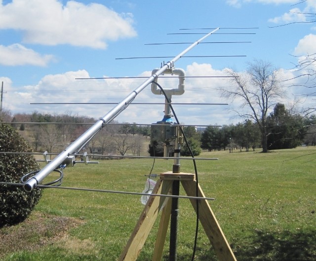
M2 2M9SSB Yagi on wood tripod with TV
rotor and
homebrew manual adjustable-elevation
mounting.
|
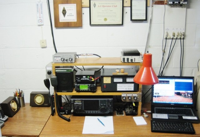
The main
station layout at K4MSG showing the HF and VHF/UHF equipment and laptop
computer, *minus* the 144 MHz amplifier (which usually sits on the top
shelf next to the 432 MHz amplifier). |
|
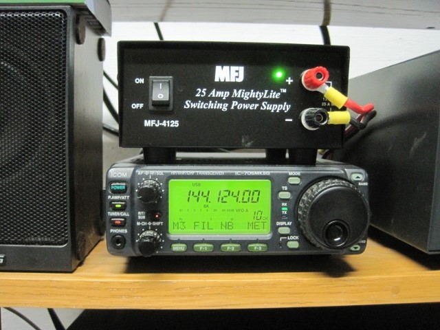
Close-up
of the IC-706MkIIG transceiver and MFJ 25-amp switching power supply.
|
 |
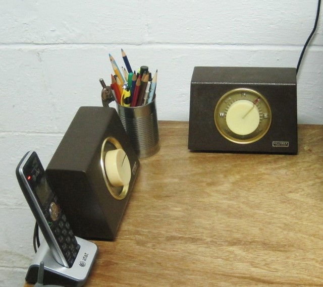 |
Rotor
control units. The left-most unit
(facing right) is the azimuth control for the single EME Yagi; the rear
control (facing front) is for the roof-mounted 144 and 432 MHz terrestrial
Yagi antennas. |
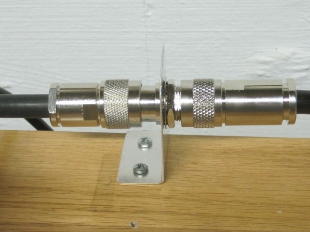 |
The Type
N interface to the IC-706. The left
(short) cable comes from the transceiver and the right cable goes to the
external EME antenna location. This
arrangement allows the EME cable to be disconnected and the cable to the
terrestrial antenna(s) connected while avoiding the use of a switch or
relay. |
|
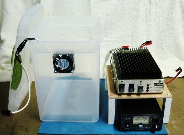
The
outdoor amplifier housing showing the MFJ 30-amp switching power supply
(lower), 144 MHz amplifier/preamp and homemade shelf next to the
housing. Note the amplifier cooling
fan mounted on the front of the housing. |
 |
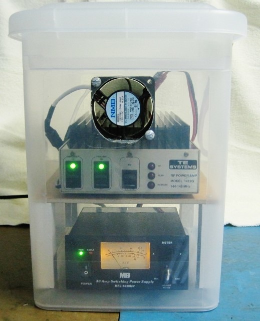 |
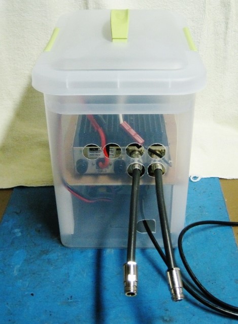
The
amplifier housing with power supply and amplifier/preamp installed and
running. The housing is a plastic
storage box available at Walmart for around $6 with suitable holes drilled
for fan mounting and cable access. It has a convenient carrying handle on the removable top cover. |
|
Rear
view of the amplifier housing; note the access holes for RF and power
cables. The row of four holes allows
airflow across the amplifier cooling fins (the fan draws air in through
these holes and blows outward). Also
note the two coax stubs on the amplifier input & output connectors;
these simplify connection of the coax lines from the transceiver & EME
antenna. Since the amplifier input
& output connectors are UHF and not waterproof while the Type N
connectors on the outer ends are waterproof if properly installed, this
arrangement ensures dry RF connections despite being quick to
connect/disconnect. |
 |
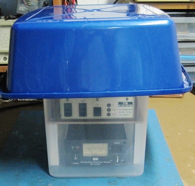 |
A
plastic basin inverted over the amplifier housing protects it from both rain
and direct sunlight and keeps the AC power connection to the extension cord
dry (it's laying on top of the housing under the basin). The basin also overhangs the rear of the
housing and protects the access holes for cables and airflow ingress. |
In
Part III we'll take a look at actual EME operation using JT65b.
EME on a Budget:
Moonbounce for the Rest of Us
By
Paul Bock, K4MSG
PART III - FIRST STEPS IN 144 MHz EME
OPERATION
SETTING UP THE SOFTWARE
If you've never used WSJT software you will need to
download it from the Internet and then READ
THE MANUAL to familiarize yourself with the screens. You'll also need to enter your own station
parameters into the WSJT program and make sure that the necessary interfaces
(serial connection, audio in, audio out, etc.) between the laptop/PC, Rigblaster,
and transceiver are correct and functioning as they should. Verify that the Dimension 4 or other "time
sync" software is keeping the PC clock corrected to less than a second of
error. There are instructions on setting
the level of the audio tones that comprise the digital signal fed to the
transceiver; follow these instructions carefully, especially the procedures for
balancing the tone levels *AND*
ensuring that no ALC action takes place as this can distort the transmitted
signal and make decoding difficult or impossible at the receiving station.
Since the WSJT manual is rather long and - not to put too
fine a point on it - a bit ponderous, I highly recommend that you also download
"W7JG's Additional Tips for Using JT65
in WSJT" which you can find at http://www.bigskyspaces.com/w7gj/JT65.pdf. Here you will
find clear and concise instructions for how to set the parameters in the JT65
screen for most efficient EME operation.
Initially, you should plan to operate only at Moonrise, especially
if you have no elevation control on the antenna. You can go to the "timeanddate.com" website
at
http://www.timeanddate.com/worldclock/astronomy.html?n=263&month=5&year=2013&obj=moon&afl=-12&day=1
to print a list of the
Moonrise times and azimuths for our area (Washington, DC) for the current
month. Make sure you choose the
"rise/set time/azimuth" display option. The times shown in the table are local time corrected for DST.
OPERATING AND COMPLETING CONTACTS
Begin your first EME operation by pointing the antenna at
the necessary azimuth point specified for Moonrise. WSJT should be set up for 144 MHz and JT65b
mode. I usually turn on the transceiver
and laptop about an hour before scheduled Moonrise, bring up the WSJT screens,
and check that Dimension 4 is controlling time correctly.
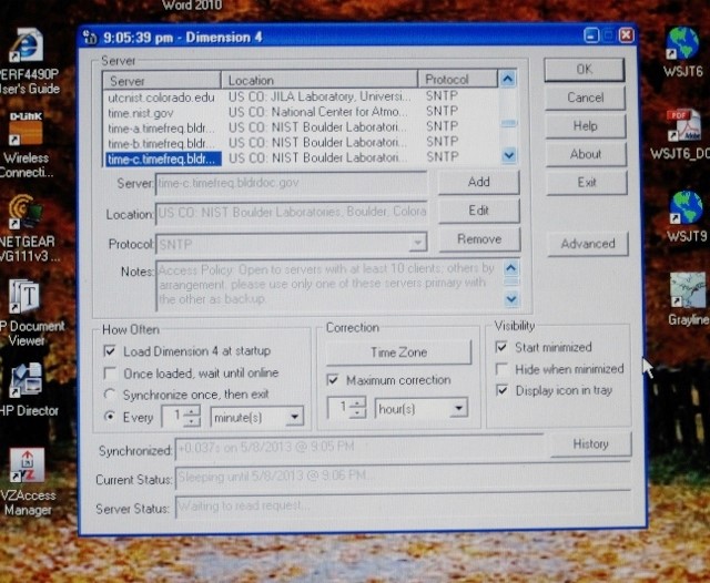 |
Dimension
4 Screen |
Just before the Moon is scheduled to break the horizon I
bring up the N0UK JT65 EME-1 chat page (It doesn't hurt to also check the JT65
EME-2 page just to see which is being currently used) and look to see who may
be active, who is calling CQ, etc. Once
the Moon rises above the horizon, tune the transceiver to where stations are
calling CQ and see if you get any decodes by clicking the MONITOR button on
WSJT. Make sure to set your RIT to the
"Doppler" offset indicated on the WSJT screen.
If you decode a CQ click the "AUTO ON" button
on WSJT but first MAKE SURE that you are transmitting the OPPOSITE time period from the CQing station, i.e., if he's sending "1st" you should be sending "2nd" and vice-versa. If you decide to try a CQ yourself make sure you alert the users on the
chat page by posting something like "CQ 144.120 2nd K4MSG
Paul FM19".
Here
is how the correct sequences look for a VALID QSO for two scenarios: Answering a CQ, and someone else answering
your CQ.
 |
|
|
| |
|
I decode: I send: I decode:
I send:
I decode:
I send:
I decode:
|
|
 |
|
|
| |
|
I send:
I decode:
I send:
I decode:
I send:
I decode:
I send:
|
|
 |
|
|
 | |
|
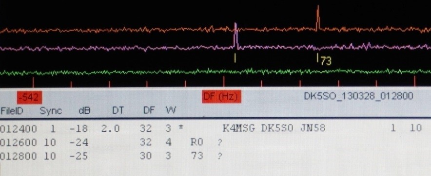
HOW SUCCESSFUL CAN A SMALL STATION BE?
Although I am a green "newbie" at EME I have been
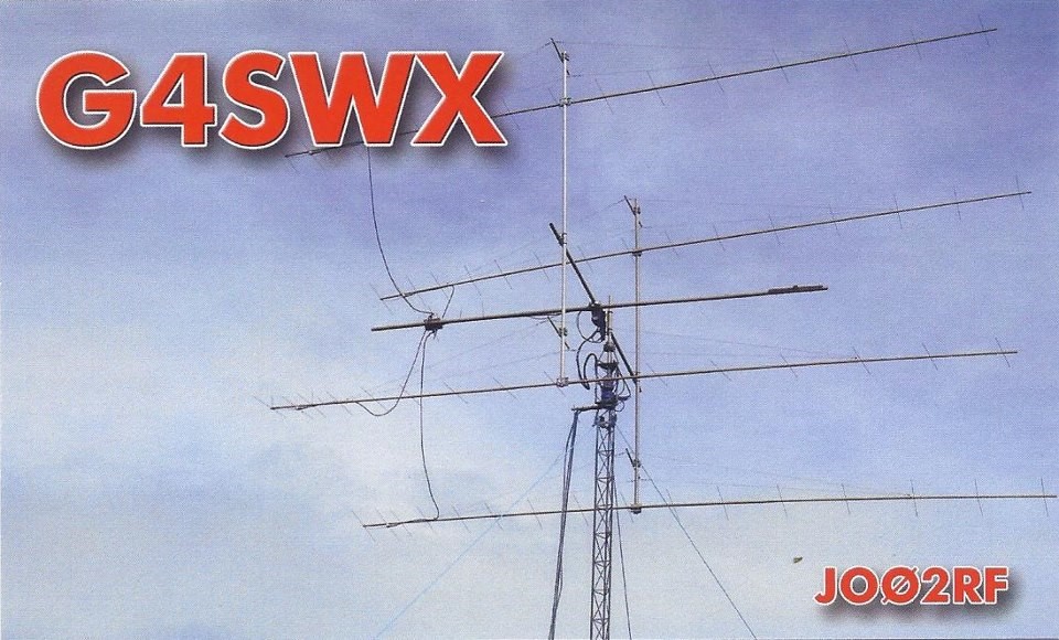
gratified with some success. Despite
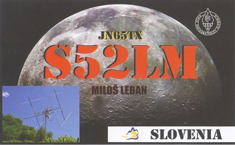
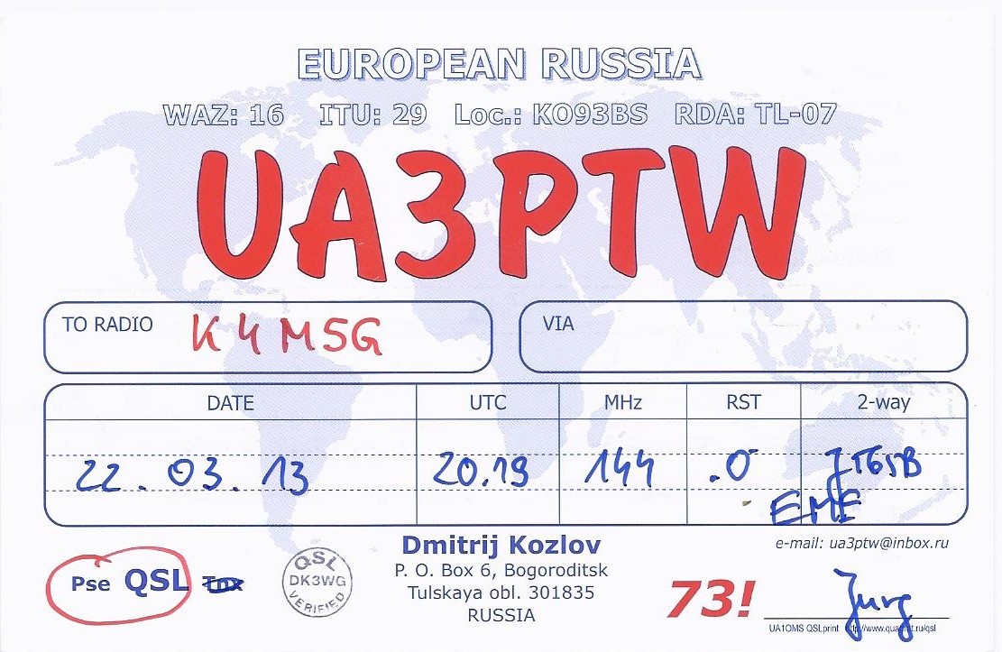
only operating sporadically during the first month I was able to complete eight
EME QSOs in six countries (DK5SO, G4SWX,
I2FAK, RU1AA, RX1AS, S52LM, SP4K, and UA3PTW). These contacts were made on different days
and under different conditions and indicate that my set-up provides repeatable
results WHEN CONDITIONS ARE FAVORABLE. This last caveat is very important because
when you are running a single-Yagi, low-power station for EME you cannot expect
to successfully achieve two-way communications via the Moon except under the
best of conditions.
|
 |
||
However, despite the limitations of using a "minimalist"
set-up and coping with the vagaries of Lunar propagation I must confess that
EME operation can become addictive. Success requires large amounts of patience and a willingness to devote
many hours to attempting to make QSOs with no guarantee of success on any given
day, but with practice and a commensurate increase in experience, coupled with
increased understanding of limitations, will come increased success - and
probably a degree of motivation to seek ways to incrementally improve one's EME
operational capability.
You will be operating on the
fringes of the ultimate weak-signal challenge for an amateur station and
success in making QSOs will place you in a select group of hams.
A future Part IV will describe a similar set-up and
results for small-station EME on 432 MHz. Stay tuned!
|
Paul Bock, K4MSG, has been licensed since 1957 and
holds an Extra Class license. He is
currently active on CW traffic nets on HF as well as small-station EME and
other weak-signal modes on VHF/UHF. Paul
is a LM of ARRL and also a member of the A-1 Operator Club, QCWA, CW Operator's
Club and several other ham radio organizations. He has earned DXCC, WAC, and WAS on HF and VUCC on 50 and 144 MHz. A retired EE who worked in the Defense and
Telecommunications fields, Paul is a Life Senior Member of IEEE and co-inventor
of a patented telecommunications device. He is also a retired U.S. Navy Master Chief Petty Officer (E-9). He holds commercial radio operator licenses
as 2nd Class Radiotelegraph Operator, GMDSS Maintainer, and General
Radiotelephone Operator, all with Ship Radar endorsement. |
| Published on K4LRG.ORG, the Home of the Loudoun Amateur Radio Group on the Internet, with permission from Paul Bock, K4MSG on May 11, 2013. |