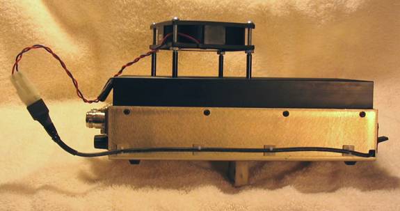
The first two parts of this series on cooling VHF "brick" power amplifiers dealt with the installation of a cooling fan on top of the unit, and a later modification to reduce the fan noise by reducing speed while maintaining adequate cooling. In this final article I'll show how the fan can be wired into the amplifier power-on circuitry so that it runs when the amplifier portion is on but not when the receive preamp is used alone.
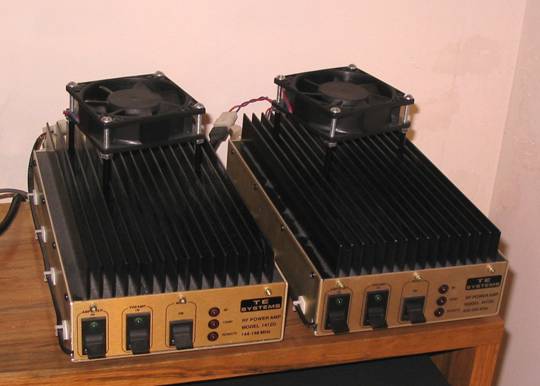
First, let me reiterate that this modification only applies to the TE Systems 14xxG and 44xxG and similar models of VHF and UHF amplifiers. These units have two power switches on the front apron, one of which turns on the receive preamp and the second of which turns on the power amplifier section. This is convenient because forced air cooling isn't necessary when using the unit for receive only.
The original fan modification involved wiring the fan to the accessory connector on the rear apron so that when the power supply was energized the fan would start running. I decided that it would be nice to only use the fan when I intended to transmit using the amplifier but not when I was using the preamp only, as when operating "barefoot" using the transceiver alone. The following photo shows the internal connections.
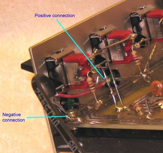
Note that all that is required is to solder the positive fan lead, in this case a red wire, to the solid wire connecting the center arm of the power switch to the PCB. The negative lead, either a different colored wire or a shield wire, is soldered to the grounding trace that runs around the perimeter of the PCB. The power cable used in this instance is Belden 8451 two-wire shielded audio cable.
The other end of the cable is connected to a Molex connector which mates with another Molex connector that is connected to the fan leads. This allows the fan to be easily removed from the unit.
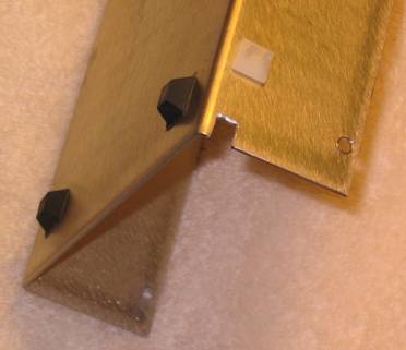
To run the cable out of the chassis without pinching, a nibbling tool was used to "nibble" a notch in the bottom cover as shown below. Note the self-adhesive nylon cable clip attached to the side of the cover.
I inserted
the two parallel resistors in the positive lead to the fan and covered
the work with a piece of heat-shrink tubing. The resultant airflow provides
adequate cooling for the amplifier. While it does run a bit warmer than
before it is still just comfortably warm to the touch after 45 minutes
of 30 seconds on, 30 seconds off operation running FSK441A. Within 5
minutes of cessation of transmitting the chassis & heat sink are cool
to the touch. The fan cannot be heard running unless you put your ear
close to it and the fan in my IC-706MkIIG normally masks the sound.