Bringing an Old Pro Back To Life
By Rick Miller - AI1V
Reston, Virginia, 12:36 AM, February 15, 2009
When we were setting up our message center for the 2009 inauguration, Dave, KE4S brought the club's TS-930S along and we hooked it up for the ODEN net on 75 meters. When we fired it up to test it, the lights came on but everything else was pretty much dead. I switched the meter on the front panel through its settings and everything was zero except when I switched it to 'Vc' (collector voltage). It buried the needle all the way to the right of the scale. I offered to take the rig home and enjoy some hours of troubleshooting, one of my favorite pastimes.
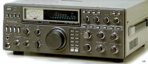
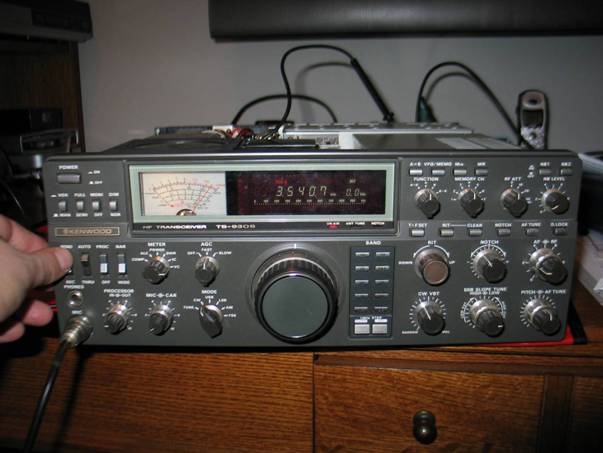
Some of you may not be familiar with this rig. From around 1980 to 1985, this was Kenwood's flagship transceiver. It was one of the first generation of rigs to have a synthesized VFO and all solid state final amplifier. Because it was at the tail end of the transition from tube finals ("peak the grid, dip the plate") there are a couple of ham history lessons about this rig that I'll point out as we go along.
My first step in troubleshooting the rig was to try to get documentation. I searched around the internet to find a service manual, and found out that somebody had actually bought the copyright to a lot of old Kenwood documentation and the only way to get it would be to pay for it. Service manuals are really nice for alignment and adjustments, but not all that necessary for troubleshooting. All I really needed was the schematic. To my surprise, the Kenwood web site had the operating manual still available for download as a pdf file! And like all respectable amateur radio operating manuals, it included the schematic (do they still do that?). It was no walk in the park, though. The pdf was created from scanning the original paper document - pdf's weren't invented when this rig was built! The schematics were originally on large format paper, so they were just on the edge of readability. It was just good enough for me to be able to read.
Actually, the fact that the rig has a built in AC supply may be unusual to many hams today. Most of us assume that we'll have to buy a 12VDC supply when we get an HF rig. For a lot of good reasons, this rig runs internally mostly on 28VDC. First of all, it takes less than half the current to produce the same amount of power as a 12V circuit. That means less heat. Even more important is that it is much easier to make a transistor amplifier linear at the higher voltage. That's why most of the top-of-the-line rigs today have a built in power supply. They run a higher internal voltage to keep the IMD products down. It also makes these rigs HEAVY! Before opening the rig, I put a static mat on my desk as much to protect the finish of my work surface as to mitigate static damage to the rig.
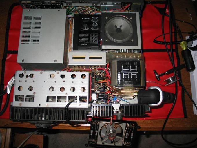
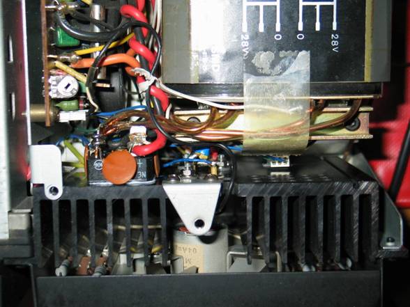
Time to dive in! Popping the cover off the rig is pretty revealing. It's crowded in there! The picture shows the rig viewed from the top
with the front panel towards the top of the picture. Starting at the upper left corner, we see a
metal shield that encloses the built in antenna tuner. Moving to the right, there is a black panel
with three knobs, a rocker switch, and a small black battery case. When the cover is on, this panel is
accessible through a sliding door. The
battery is to back up the VFO memories (all eight of them!). The three knobs are VOX gain, delay, and
anti-VOX adjustments. The switch, which
is labeled 'CAL ON/OFF', is one of our history lessons. Back in the days when you tuned a radio using
a knob hooked up to a variable capacitor or inductor instead of an optical
encoder changing the multipliers and dividers in a digital PLL, you sometimes
had to take your dial frequency with a grain of salt. For the most part, reading a dial on an old
radio would not be sufficiently accurate to work right up to the edge of a
band. So these radios usually included a
harmonic rich crystal controlled oscillator that could inject fairly well
calibrated 'birdies' into your receiver. When you switch the
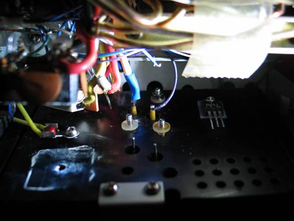
Continuing clockwise from there, we have the built-in speaker. Below that you can see the beefy power transformer. The finned black panel below that is the heat sink for the regulator pass transistors. Note that in the picture I've removed some of the components from that heat sink to be able to get at things a little better, and I've wedged a small flashlight between the heat sink and the power transformer. I've also detached the fan assembly, which is dangling below the heat sink by some wires. Moving left from there we find another shielded enclosure attached to an even larger heat sink. That is the 200W (input) PA. Nestled (stuffed?) between the PA enclosure and the power transformer is the voltage regulator circuitry. It has about a half dozen 10 gauge wires soldered to it making it very tough to work around. Finally, near the middle of everything is a smaller rectangular metal enclosure (in the picture it looks like it has a couple of black stripes). This is the support for two fairly large filter capacitors.

Here is the section of the schematic that shows the power supply (yes, it really is that fuzzy). My first suspicion was that a filter capacitor had failed. This rig is very infrequently used and electrolytic capacitors are notorious for failing when they are fired up after long periods with no voltage applied to them (use 'em or lose 'em!). The quickest way to check that out was to put an oscilloscope on the positive lead of the cap to see if there was any ripple. What I found was a very pure DC level at 40 volts. So the caps are okay - good! Replacements of the right size and value could be hard to find. So at this point I know the transformer, the rectifier and the capacitors are working at least under no-load conditions. The next components downstream in the circuit are the two power transistors, Q1 and Q2. These are hooked in parallel to share the current and are responsible for dropping the unregulated voltage from the filter capacitors down to 28VDC under control of the circuitry at the bottom of the schematic. If they are working, there should be around 40V on the collectors and 28V on the emitters. Well the 40V on the collectors was okay, but the emitters were also at 40V! I now suspected either a faulty (shorted) transistor or a problem in the regulator circuit that left the transistors turned all the way on. It was time to disconnect the power, dig in, and do some ohmmeter exploration.
Since the transistors are in parallel and I suspected a short, I had to disconnect at least one of the transistors to see which one (if either) had failed. The transistors are mounted to the back of the heat sink and have their two leads protruding through holes in the heat sink with wires soldered to them. The only problem was the heat sink was bolted in place so I could hardly even see the connections, much less get at them with a soldering iron. Even when I unbolted the heat sink from the chassis, the heavy wires soldered to the transistors and the bridge rectifier (also bolted to the heat sink) held it firmly in place. The first thing I did was remove the screw attaching the bridge rectifier to the heat sink. In the photo you can see the square white smudge from the heat sink compound where the rectifier was attached. That gave me enough play so I could unsolder the top transistor, which gave me enough play so I could get to the bottom transistor. I don't know, but I think surgery must be like this!
Using an ohmmeter, I checked the resistance between the emitter and collector of each transistor. The first one showed no shorts. The second one, however, showed a short between the collector and emitter. I reversed the ohmmeter leads just to be sure and the short was still present. I found at least one problem! Now it's time to pull the bad part. That was done by simply unbolting the transistor, being careful to catch washers, nuts, and insulators as they came off. With a little needle-nose persuasion, the transistor popped right off the back of the heat sink.
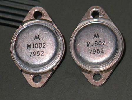
Then I got a REAL history lesson. The date code on the transistor was '7952' which indicates that these puppies will be 30 years old this December! I found a replacement transistor on the web and decided to order two. They were less than $15 each and at those prices, I had no qualms about retiring even the one that wasn't shorted.
Fast forward 5 days. The UPS guy drops off an envelope with two eager young semiconductors inside! I have two challenges now. The first is to do some really tight quarters soldering. The second is to be sure I remember where all the wires go! This photo shows the assembly after re-connecting the bottom transistor. The two transistor leads can be identified by the yellow insulation on them that keep them from contacting the heat sink. The small purple wire on the right is attached to the base lead. The heavy orange wire on the left is attached to the emitter. I added some blue heat shrink tubing since the 30 year old insulation was getting a bit brittle, especially after being re-heated a few times. Those of you that know about transistors may be asking yourself, what about the collector lead? On these devices, the collector is connected to the metal case of the device. The next step in the assembly will be to attach a double-ended solder lug to the two screws sticking out from the nylon insulators, just next to the soldered leads. Those screws are used to mount the transistors and connect to the case/collector.
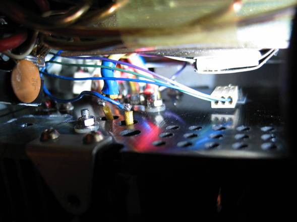
As I work on up to the top transistor, things get squeezed pretty tight. This shows what it looks like after I've connected the second transistor and re-attached a connector to a smaller power device over on the right. The bridge rectifier is not yet attached. It is the black plastic block on the left with the disk ceramic capacitor attached to it. Immediately below it you can see the threaded hole in the heat sink where its mounting bolt goes.
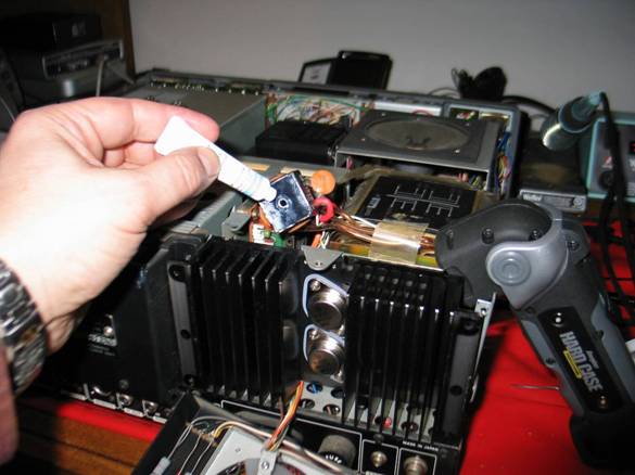
Since the thermal compound on the rectifier is also a little long in the tooth, I apply some fresh. Here you can also see the cases of the two new transistors attached to the back of the heat sink. Also note the flashlight wedged in the gap where I've been doing all the surgery - you can never have too much light!
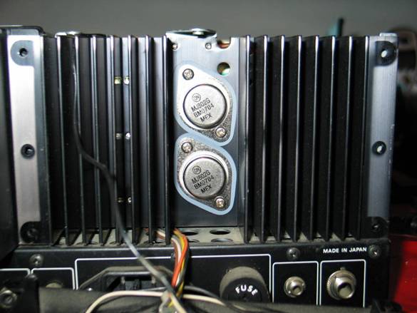
Here is a better view of the new transistors on the back of the heat sink. They are mounted on thermal insulators. That's because the heat sink is bolted to the chassis, which is at ground potential, and the transistor cases (collectors) are at 40V. It's all ready to be bolted back in place. Note the date code on the new transistors. In January of 2037, someone could look at this rig and say "Wow, those transistors are 30 years old!"
Here is another top view with everything back in place. The rectifier is now bolted to the heat sink on the left, and the heat sink and fan assembly are bolted to the chassis. Time for the smoke test!
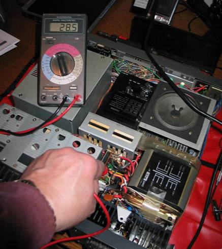
I love it when a plan comes together! Where we used to have 40V unregulated, we now have pretty close to 28V.
Smoke test number 2: hook up a dummy load and key the transmitter. The meter switch is in the 'Vc' position and is much happier displaying 28V than it was trying to show 40V.
Switching the meter to 'power' shows a respectable 130W out. This was corroborated on an external meter.
So now let's have one last quick history lesson before I sum things up. The meter switch on this rig has positions for 'Ic' and 'Vc' which stands for 'collector current' and 'collector voltage'. Why? When this rig was introduced, regulations concerning transmitter power specified "input power", or the total power into the final stage of the power amplifier, and amateurs were required to log the power used on each contact. The meter lets the operator directly observe collector current and collector voltage and using good old Ohm's Law, multiply them together to get input power. (Technically, one would have to add the power coming out of the driver section to that number to get total input.) So what's the difference between input power and output power? Here's a hint - remember that large heat sink on the PA? That's where the leftover watts go.
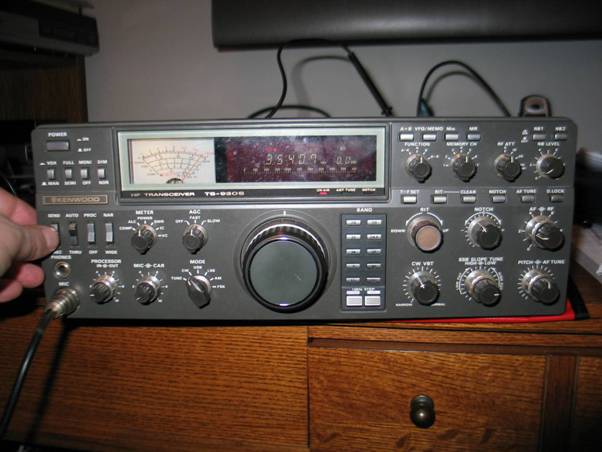
So what's the status of this rig? First of all, the receiver still seems pretty hot. I did some ad hoc A/B testing against my K3 and it's definitely working well. Both heat sink fans and the thermal sensors that control them seem to work well, though the PA fan is a little noisy. The rig is, however, suffering from 'old rig syndrome'. There was lots of dust and debris inside, most of the potentiometers are pretty noisy and some of the switches are a little jumpy at times. Whoever hangs onto this rig should consider storing it in a plastic bag to keep the moisture, dust, and varmints out. There is an intermittent connection somewhere in the microphone or audio input circuitry (it could just be another dirty switch or pot). The antenna tuner seems to work, though I didn't do any rigorous testing. If someone could clean up the pots and switches and do a good alignment, I think we've got a useful radio that could last another 30 years.
73, Rick - AI1V
NNNN