Repairing Unadilla (W2VS) 40m Antenna Traps
By Paul Bock,
K4MSG of Hamilton, Virginia, November 4, 2011
Click here for other articles by Paul posted to the LARG Internet Site
In late October of 2011 my multiband trap dipole antenna, which is based on the classic design by W3DZZ ("The ARRL Antenna Book", thirteenth edition, 1974, p. 185) and uses a pair of 40-meter Unadilla Model KW-40 traps, suffered an unusual failure. Part of one of the traps separated, causing the coil to unwind completely and making my dipole antenna several feet longer on one side. This significantly detuned the antenna and rendered it non-functional. After some analysis of the failure and a little experimental repair work I was able to restore the trap to functionality and resurrect the antenna. This article describes the failure mode and the method used to repair the trap, and offers some cautions for anyone who experiences a similar failure and decides to try this repair approach. |
TRAP CONSTRUCTION AND FAILURE
The Unadilla trap is constructed with two concentric lengths of aluminum tubing separated by an insulating layer, thereby forming the parallel capacitor, with both tubes housed inside a larger-diameter blue plastic housing. Just over 9 feet of #14 tinned copper wire is wound over the outside of the plastic housing to form the coil. Each end of the coil is connected to one of the two metal tubes and the antenna wire connections are made at the same points on each end of the trap. Photo 1 shows a typical trap; note the crack in the outer housing.
The failure occurred when the outermost metal tube was pulled out of the blue housing by the strain from the antenna, causing the coil to unwind completely. Photo 2 shows the damaged trap.
CAUSE OF FAILURE
Examination of the damaged trap revealed that the plastic housing had cracked axially (i.e., along the longitudinal axis) from end to end and down to the surface of the outermost metal tube (Photos 1 & 2 depict axial cracks in both trap housings). Why this crack occurred is still a mystery, but it happened to both traps so I suspect a flaw or inherent weakness in the material used to construct the blue shell. Although the outermost metal tube was epoxied to a cork filler that ran the length of the innermost metal tube (see Photo 3 which depicts the end of the innermost tube and the cork filler) the loss of friction due to the crack in the housing probably placed all of the antenna strain on the cork filler and it eventually separated, thereby allowing the outer metal tube to pull out of the housing and subsequently unwinding the coil.
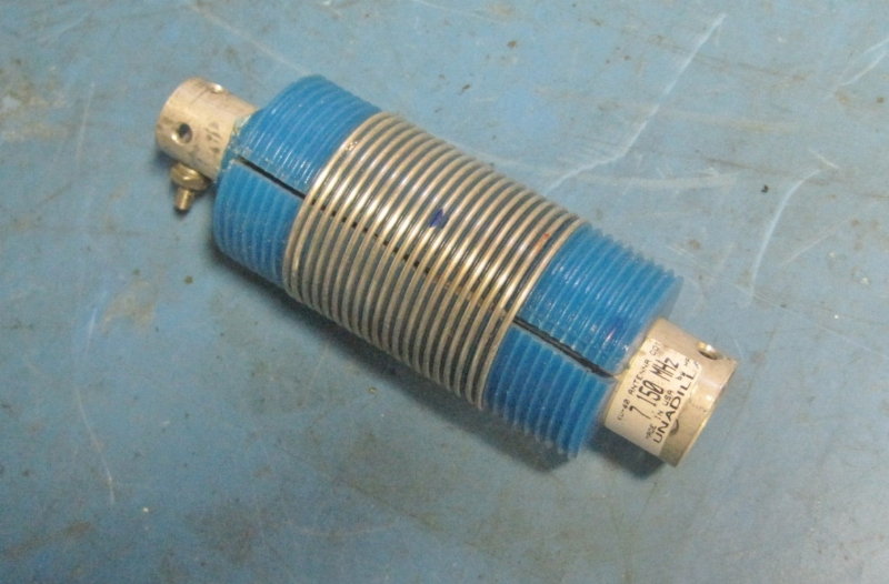
Photo 1: A typical Unadilla KW40 antenna trap. Note the axial crack in the blue housing.
REPAIR APPROACH
I decided that I needed to do three things to attempt repair of the defective trap:
1) Re-epoxy the outer metal tube back into the housing.
2) Fill the axial cracks in both traps with some type of weatherproofing sealer to prevent moisture ingress.
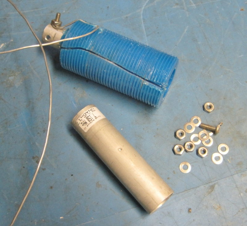
| Photo 2: The damaged antenna trap showing the outermost metal tube (which pulled completely out of the trap assembly) and a portion of the coil which unwound completely from the blue housing. The hardware was removed from the trap. Note that this trap is cracked in similar fashion to the trap in Photo 1 (which did not fail). |
3) Reinforce the aluminum tubes in some manner so that they could not pull out of the housing even though the housings were cracked and substantial friction that would have tended to keep the outermost metal tube in place was lost.
Step 1 was accomplished by first cleaning out the cork residue inside the closed end of the outer metal tube. Then a quantity of two-part epoxy was daubed onto the exposed end of the smaller (inner) metal tube and the outer tube was tapped back into the housing using a plastic mallet, taking care to ensure that the holes in the end of the tube were properly aligned as originally installed. The exposed length of the outer tube was checked against the undamaged trap to ensure that the tube was tapped fully into the housing.
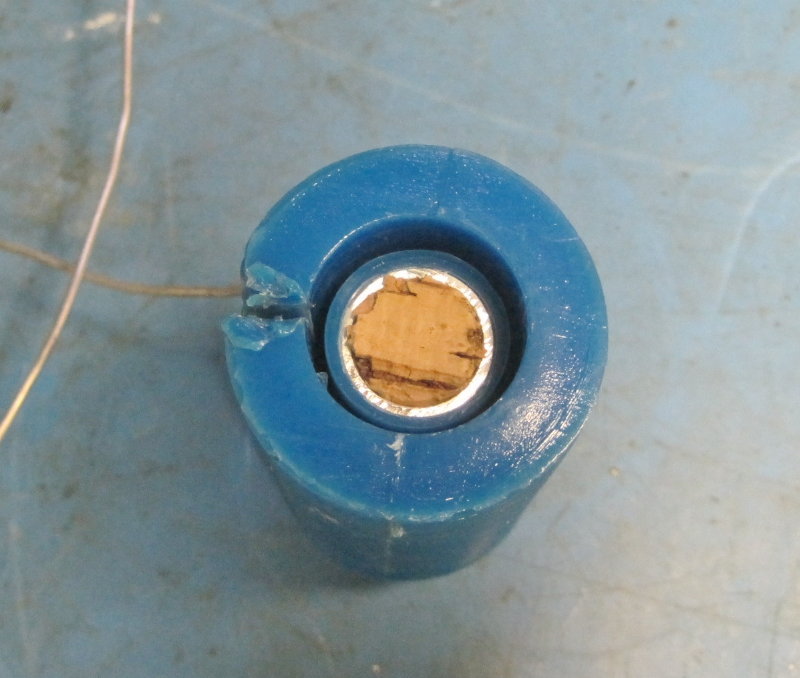
| Photo 3: View of the open end of the damaged trap showing the innermost metal tube and the cork core. The missing portion of cork was stuck inside the outermost metal tube. This indicates that because the blue housing cracked open and separated along its entire length, the cork filler was bearing the brunt of the axial load on the trap and finally gave way. The exposed cork in the photo was coated with epoxy and the outer metal tube driven back into the trap body. |
After allowing the epoxy to set overnight, clear silicone waterproof caulk was forced into the radial crack in the housing using a caulking gun, making sure that it penetrated all the way to the exposed surface of the outer metal tube and oozed from the two ends of the housing. Excess residue was cleaned off and
the caulk was allowed to dry for several hours.
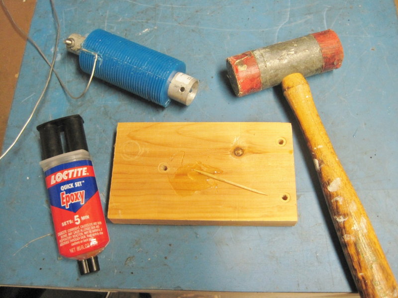
| Photo 4: The damaged trap after reinsertion of the outer metal tube. Tools for this operation included 2-part epoxy, a board (and toothpick) for mixing the epoxy and serving as a base while driving the tube back into the trap, and a plastic hammer to do the driving. |
Caulking was also applied into the crack of the undamaged trap but without unwinding the coil, which necessitated carefully forcing the caulk in between the wire turns to ensure that it penetrated fully into the crack.
After rewinding the coil of the damaged trap (the coil wire was actually 1.5 inches too long due to "stretching" when it unwound and was subjected to the strain of being part of the antenna wire) and connecting the coil ends to the two metal tubes, both traps were tested to ensure that they were resonant in the 40-meter band. Since I don't have a dip meter the traps were successively installed in series with an RF signal generator and a 50-ohm load installed across the output. Using an oscilloscope to monitor signal level across the load, and a frequency counter to indicate the exact frequency of the generator output, the generator was tuned over the frequency range from 6 to 8 MHz and the point of maximum attenuation (or "dip") in the signal was noted on the frequency counter display. Both traps were found to be resonant in the low end of the 40 meter band, albeit about 200 kHz apart in frequency. Figure 1 is a simple diagram of the test set-up.
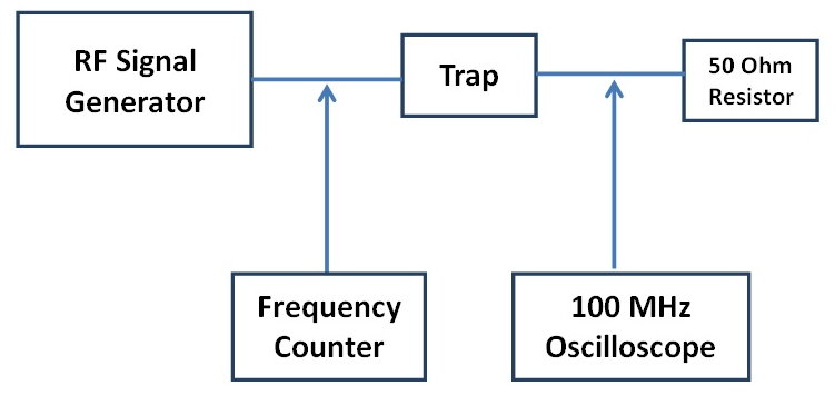
| Figure 1. Test set-up for checking trap resonant frequency. |
REINFORCING THE TRAPS
After mulling over the "pull strength" problem I decided that a reasonable approach was to drill a radial hole through the trap and insert a non-conductive "pin" completely through the trap - and both metal tubes - to prevent the latter from pulling out of the housing. This approach entailed three risks:
1) Since I would be drilling through two concentric metal tubes separated by an insulating layer there was the danger that bits of metal might cause a short circuit across the "tubing capacitor", so extra care during drilling would be required.
2) Drilling through the insulating layer separating the metal tubes would reduce the dielectric strength between the two "capacitor plates" (e.g., the two metal tubes) to that of air, undoubtedly reducing the power rating of the trap well below the original 1 kW rating. However, since I only operate at the 100-watt level this seemed an acceptable risk.
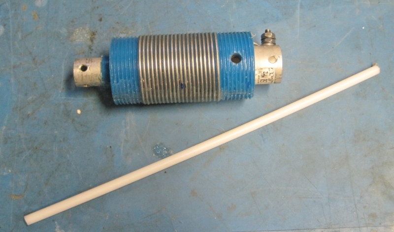
| Photo 5. Note the 1/4-inch hole drilled into the body of the non-failed trap. The nylon rod shown in this photo was used to "pin" the metal tubes into the trap body. |
3) Drilling through the walls of both tubes would reduce the capacitance slightly and raise the resonant frequency of the trap; however, the amount of metal removed would be small and therefore the change would probably be of minimal consequence.
With the above caveats in mind, I drilled 1/4-inch diameter radial holes in each of the traps and inserted 1/4-inch nylon rod into the holes. Photos 5 and 6 depict the hole after drilling and after filling with a 1/4-inch nylon pin. The holes were drilled only a small distance at a time, with the drill bit pulled all the way out of the hole frequently to remove metal bits from the hole. After drilling, the holes were brushed with a small, stiff brass wire cleaning brush from a revolver-cleaning kit, to remove any metal or other residue from the holes. The holes were then swabbed out with Q-tips dipped in 91% Isopropyl alcohol and allowed to dry thoroughly.
A nylon rod was inserted into each hole and the rods fit fairly snugly - in fact, they had to be lightly tapped into place - so there seems little danger that they will work their way out of the holes,
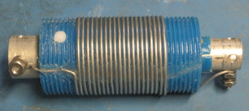
| Photo 6. The failed trap after repair. Note the reinserted outer metal tube, the silicone filling the crack, the nylon pin through the trap body, and the rewound coil. |
especially since the antenna under tension will cause the rod to be held tighter by the axial strain on the metal tubes. As a precaution against water migration the ends of the two nylon "pins" were sealed with clear silicone.
TESTING THE REPAIR HYPOTHESIS
With the traps repaired it was time for re-installation and test. The antenna was lowered and the traps reinserted (the antenna had been "jerry-rigged" after trap removal as a 110-foot temporary dipole). Tests on 80 & 40 meters showed the antenna's performance characteristics to be the same as before trap failure. Operation at 100 watts showed no signs that the drilled-through capacitor tubes might be arcing over
CONCLUSION AND A CAVEAT
The results indicate that the procedure described is a reasonable way to repair a similar failure, but with a caveat: If using high power there is the possibility of arc-over between the metal tubes at the points where the radial hole is drilled, but operation at 200 watts and below should not be a problem.
The issue of why the trap housings cracked completely open still remains unanswered.
NNNN